Z31/droppingresistors: Difference between revisions
Inline image refs: rewrite to local archive; clean empty image artifacts |
CleanupBot (talk | contribs) Rewrite 7 dev.z31library.com link(s) to z31library.com |
||
| (2 intermediate revisions by 2 users not shown) | |||
| Line 1: | Line 1: | ||
{{ImportedFrom|site=Xenonzcar|title=Z31 Dropping Resistor Install to run an 88-89 ECU with low-Impedance injectors|url=https:// | {{ImportedFrom|site=Xenonzcar|title=Z31 Dropping Resistor Install to run an 88-89 ECU with low-Impedance injectors|url=https://z31library.com/xenonzcar_archive/z31/droppingresistors.html|archive=https://z31library.com/xenonzcar_archive/z31/droppingresistors.html|fetched=2026-05-15}} | ||
== Z31 Dropping Resistor Install to run an 88-89 ECU with low-Impedance injectors == | |||
This is by no means a perfect solution to adapting an ECU with injector drivers designed for high-impedance injectors (88-89) to run low-impedance injectors (84-87). However, it appears to work well for everyone nonetheless. By now you should have already figured out which [[Z31/ECUdifferences|ECU and injectors as well as oxygen sensor]] you are using as well as [[Z31/Rewirefuelinjectors php|re-wired your injectors to factory specs]]. | |||
'''Parts and tools needed:''' | '''Parts and tools needed:''' | ||
* Wire strippers | * Wire strippers | ||
* Six 10W 6-10ohm wire wound resistors (available from | * Six 10W 6-10ohm wire wound resistors (available from [http://www.digikey.com Digi-key], [http://www.jimwolftechnology.com JWT], among others) | ||
[http://www.digikey.com Digi-key],[http://www.jimwolftechnology.com JWT], among others) | * Electrical tape | ||
* Heat-shrink tubing | * Heat-shrink tubing | ||
* Soldering iron and 60/40 rosin core solder | * Soldering iron and 60/40 rosin core solder | ||
'''Process:''' | '''Process:''' | ||
Disconnect the battery and remove the ECU from the passenger side kick-panel and remove the connectors. Pins 101-106 lead to the injector wires; you need to solder resistors in line on each one of these wires. The bottom connector (as the ECU sits in the car) contains pins 101-106 on the end of the connector opposite the locking tab. Notice the wires here, they are green in my harness (and most likely yours also). | Disconnect the battery and remove the ECU from the passenger side kick-panel and remove the connectors. Pins 101-106 lead to the injector wires; you need to solder resistors in line on each one of these wires. The bottom connector (as the ECU sits in the car) contains pins 101-106 on the end of the connector opposite the locking tab. Notice the wires here, they are green in my harness (and most likely yours also). | ||
Your resistors will probably look something like this: | Your resistors will probably look something like this: | ||
https://z31library.com/xenonzcar_archive/z31/images/dropping%20Resistor/res4.JPG | |||
Wrap some tape around the resistor itself and bend the leads around 180 degrees. Tin the leads and secure them to the resistor in the middle using a zip tie and/or electrical tape. I soldered little sections of wire onto mine to make the installation/removal process easier. Do it however you see fit, just make sure you don't have any chance of a short: | Wrap some tape around the resistor itself and bend the leads around 180 degrees. Tin the leads and secure them to the resistor in the middle using a zip tie and/or electrical tape. I soldered little sections of wire onto mine to make the installation/removal process easier. Do it however you see fit, just make sure you don't have any chance of a short: | ||
https://z31library.com/xenonzcar_archive/z31/images/dropping%20Resistor/res1.JPG | |||
Locate the 12 prong plug at the ECCU and Clip the Green wires a couple inches from the connector, tin the wires (notice where mine were clipped and re-soldered): | |||
https://z31library.com/xenonzcar_archive/z31/images/dropping%20Resistor/res2.JPG | |||
Solder the resistors inline, heat shrink the ends and then wrap with electrical tape: | |||
https://z31library.com/xenonzcar_archive/z31/images/dropping%20Resistor/res3.JPG | |||
=== Sources used on this page: === | |||
* [https://z31library.com/xenonzcar_archive/z31/fsm.html 1984-1988 Nissan 300ZX Factory Service Manual] | |||
* [http://www.redz31.net Writen by: Jason Butts -AKA- Jason84NA2T] | |||
[[Category:Imported from Xenonzcar]] | [[Category:Imported from Xenonzcar]] | ||
Latest revision as of 22:54, 20 October 2026
Imported page. This page was converted from an archived copy of "Z31 Dropping Resistor Install to run an 88-89 ECU with low-Impedance injectors" (Xenonzcar, fetched 2026-05-15). The conversion was mechanical, so tables, links and formatting may contain conversion artefacts. Compare against the archived copy if something looks wrong. The content belongs to its original authors.
Z31 Dropping Resistor Install to run an 88-89 ECU with low-Impedance injectors[edit]
This is by no means a perfect solution to adapting an ECU with injector drivers designed for high-impedance injectors (88-89) to run low-impedance injectors (84-87). However, it appears to work well for everyone nonetheless. By now you should have already figured out which ECU and injectors as well as oxygen sensor you are using as well as re-wired your injectors to factory specs. Parts and tools needed:
- Wire strippers
- Six 10W 6-10ohm wire wound resistors (available from Digi-key, JWT, among others)
- Electrical tape
- Heat-shrink tubing
- Soldering iron and 60/40 rosin core solder
Process:
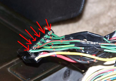
Disconnect the battery and remove the ECU from the passenger side kick-panel and remove the connectors. Pins 101-106 lead to the injector wires; you need to solder resistors in line on each one of these wires. The bottom connector (as the ECU sits in the car) contains pins 101-106 on the end of the connector opposite the locking tab. Notice the wires here, they are green in my harness (and most likely yours also).
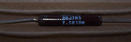
Your resistors will probably look something like this:
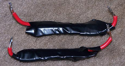
 Wrap some tape around the resistor itself and bend the leads around 180 degrees. Tin the leads and secure them to the resistor in the middle using a zip tie and/or electrical tape. I soldered little sections of wire onto mine to make the installation/removal process easier. Do it however you see fit, just make sure you don't have any chance of a short:
 Locate the 12 prong plug at the ECCU and Clip the Green wires a couple inches from the connector, tin the wires (notice where mine were clipped and re-soldered):
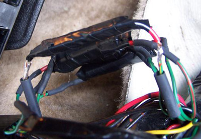
 Solder the resistors inline, heat shrink the ends and then wrap with electrical tape: